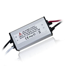
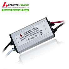
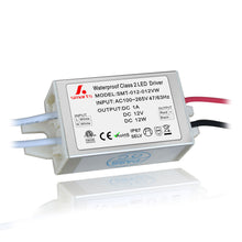
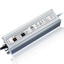
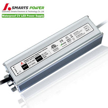
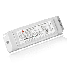
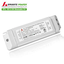
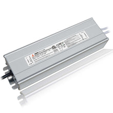
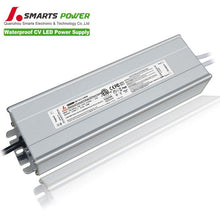
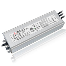
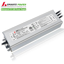
5 in 1 Dim J-BOX LED Driver 200W
This series offers a wide range of wattage from 30W to 384W. The 200w led driver has the characteristics of high power factor? 0.98 and effiency up to 0.9. We would to recommend 12v 24v LED strips when you are looking for compatible lights.
| model | SMT-012-200VTDHV2 (1.0 version) | SMT-024-200VTDHV2 (1.0 version) | |
| SMT-012-200VTDHWV2 (2.0 version) | SMT-024-200VTDHWV2 (2.0 version) | ||
| Output | DC Voltage | 12V | 24V |
| Rated Current | 16.67A | 8.33A | |
| Rated Power | 200W | 200W | |
| Voltage Tolerance | ±0.5V | ||
| Voltage Regulation | ±0.5% | ||
| Load Regulation | ±2% | ±1% | |
| Input | Voltage Range | 110-277VAC | |
| Frequency Range | 47-63Hz | ||
| Power Factor @ full load | 0.98@120VAC 0.97@277VAC | 0.98@120VAC 0.95@277VAC | |
| THD(Typ.)@ full load | <20% | ||
| Efficiency @ full load | 83% @120Vac 87%@277Vac | 86% @120Vac 88%@277Vac | |
| AC Current(Max.) | 2.3A@100Vac | ||
| Inrush Current (Typ.) | 15A, 50%, 1.4ms @120Vac 30A, 50%, 1.4m,s @277Vac | ||
| Leakage current | <0.50mA | ||
| protection | Short Circuit | shut down o/p voltage, re-power on to recover after fault condition is removed | |
| Over Loading | ≤120% constant current limiting, auto-recovery | ||
| Over temperature | 100℃±10℃ shut down o/p voltage, automatically recover after cooling. | ||
| Environment | Working TEMP. | -40~+60℃ (see below derating curve) | |
| Working Humidity | 20~90%RH, non-condensing | ||
| Storage TEMP. Humidity | -40~+80℃,10~95%RH | ||
| TEMP .coefficient | ±0.03%/℃(0~50℃) | ||
| Vibration | 10~500Hz, 5G 10min./1 cycle,period for 60min. each along X,Y,Z axes | ||
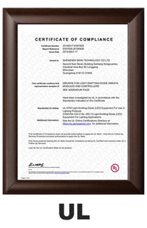
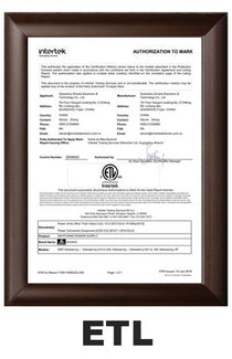
| Safety&EMC | Safety standards | UL8750+UL1310 | |
| Withstand voltage | I/P-O/P:1.88KVAC | ||
| Isolation resistance | I/P-O/P:100MΩ/500VDC/25℃/70%RH | ||
| EMC EMISSION | FCC Part 15 B | ||
| Others | Weight | About 1.8Kg | |
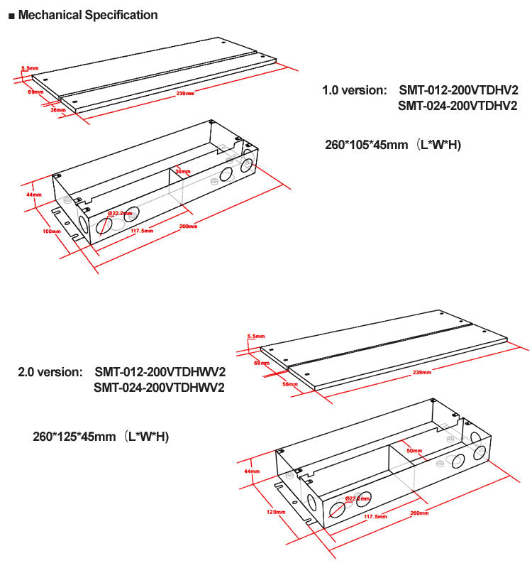
| Size | 1.0 version: 260*105*45mm / 2.0 version: 260*125*45mm | ||
| packing | 10PCS/CTN (L*W*H) | ||
| Notes | 1. All parameters if NOT specially mentioned are measured at 120VAC input , rated load and 25℃of ambient temperature. | ||
| 2. To extend the driver's using life ,please reduce the loading at lower input voltage. | |||
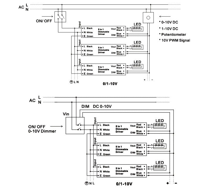
- Inputwire Black and White to be connected?to?AC?L and N ,Green wire go ground,
- Output wireRed to LED Positive side (+) , Black ?to LED Negative side (-).??
- Dimming cable DIM (+) Purpleto 0/1-10V dimmer signal(+ ),DIM (-) Grey?to 0/1-10V dimmer signal (-) ?
- Please make sure your connect these correctly otherwise your product will not function correctly and could be damaged.
¡ö?Connecting Diagram
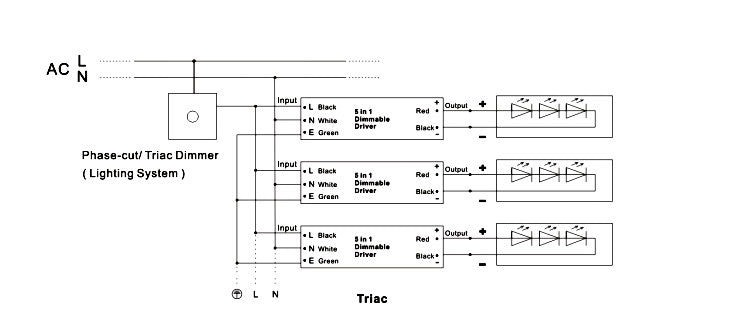
Using TRIAC/Phase cut dimming
1.The Pulse-Width Modulation (PWM) of output voltage can be adjusted through input terminal of the AC phase line(L) by connection a phase /Triac dimmer of lighting system.
2.Work with forward phase /leading edge ,MLV and?reverse phase /trailing edge ,ELV,TRIAC dimmers.
3.Please try to use dimmers with power at least 1.5 times as the output power of the driver.
?Using 0-10/1-10V dimming
?